New CPU Layout
After I updated the Program Counter & Clock board the other day, I decided to rebuild the RAM board and add the board for the LED readouts so that I have one location for the Address, Instruction and Accumulator LED's. To do this I had to pull apart most of the work I had done previously which means I'm a little farther behind than I was a week ago. On the upside, because as I'm going through the cleanup I'm improving the wiring and installing decoupling caps so when It's finally done it should run glitch free.
To date I have wired the Program Counter to the Address Bus of the Instruction RAM and the Instruction RAM Data to the ROM and Multiplexor on the Control board. Next up, I'll wire the Program RAM into the Multiplexor and Accumulator Data Bus.
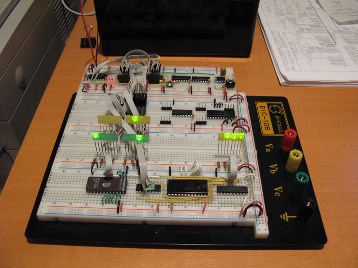
Above, the new layout in run mode. It isn't actually running a program, it's just cycling junk data that is in the Instruction RAM chip.